It's a common occurrence, you get a call out to a scale, the loadcell is damage or the base is broken and you are pretty sure it's been overloaded - but there's no proof. The customer is always right. Yes, it's true but sometimes they don't know exactly what happened themselves...let's talk Peak Overload!
When it comes to diagnostics, for Engineers in the scale trade,
"Peak Overload" can be a real Godsend! Knowing whether a scale has been overloaded can really help with those awkward "warranty or not" discussions and all Baykon BX2X indicator
models feature this useful diagnostics feature as standard.
What is Peak Overload on a Weighing Scale and how can I tell if a scale has been overloaded?
Peak Overload is the highest mV reading that the indicator recorded from the loadcells during a weighing. When the loadcell is put under strain the mV reading across the strain gauge increases. Baykon indicators can record the maximum mV reading that occurs along with the time and date of when it happened. This allows a Scale Engineer to confirm if and when the scale has been loaded beyond the it's correct capacity. If the engineer is having to replace a damaged loadcell or another part of the scale due to a suspected overload, this valuable tool can be a vital bit of evidence in settling disputes over warranty or misuse and abuse.
How to use the diagnostics feature on the BX2X indicators and see the Peak Overload
The video above shows how to access the Diagnostics Mode in Baykon BX23, BX24 & BX25 Weight Indicators and the guide below takes you through it step by step.
1.Turn on your Baykon BX23, BX24, BX25
2.Enter password (1111) for BX24 & BX25 or enter MEMORY, ZERO, TARE, ZERO for BX23
3.Select (SERVICE MENU)
4.Select option 92 (HISTORY)
5.Select 921 (PEAK HOLD)
6.This will display a specific date, time and overloaded weight on the screen. Using the arrow keys, you can cycle through historic records.
Weight Simulators - a great device for weighing engineers and a "must have" in your tool box!
The
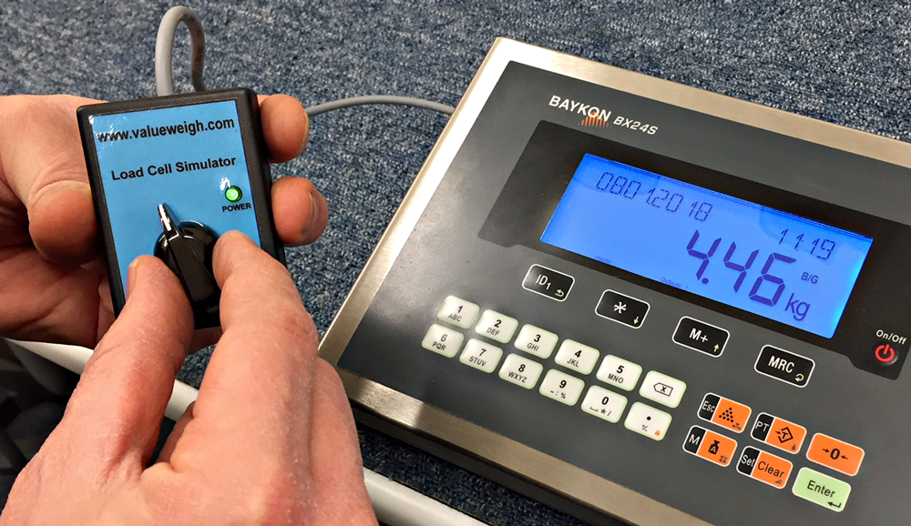
VWSIM and VWSIM+ Loadcell Simulators are designed to imitate a scale base during repair, testing or demonstrations. This is ideal for quickly checking weight indicators without a scale (during service work or calibration) or for sales reps to demonstrate indicators during visits.
Calibration using a VWSIM is easy - simply turn the potentiometer knob to vary the simulator mV output and perform a standard calibration. The loadcell simulators are available with flying leads or 9-pin D connectors (female), making them ideal for all weight indicators.
|
The D-connector terminal outputs are:
1: + Excitation
2: - Signal
3: NC
4: - Sense
5: Shield
6: - Excitation
7: + Signal
8: NC
9: + Sense |
The flying lead output cable colours are:
Brown: + Excitation
Yellow: - Signal
White: - Excitation
Green: + Signal |
The
VWSIM loadcell simulators are suitable for use with indicators that provide a 5VDC to 10VDC excitation voltage.
The
VWSIM+ has three buttons that provide fixed mV outputs to the weight indicator. If one of these buttons is pressed, the voltage corresponding to that button (0, 5mV, 10mV or 20mV) will appear at the simulator output. When the button is released, the voltage which corresponds to the position of potentiometer knob will appear at the simulator output. The output voltage of the simulator is the same as that of a standard loadcell which is 2mV/V.
Remember: When the potentiometer knob is turned fully left, the voltage at the simulator output is negative (less than the voltage from pressing the -0mV button.) When the potentiometer knob is turned fully right, the voltage at the simulator output is bigger than the voltage from pressing the 20mV button. As such, it is possible to imitate the signal output from the loadcell beyond the range of calibration (e.g. under or over capacity). The excitation voltage supplied to the VWSIM+ can be any value between 5VDC and 15VDC.
How to wire a BX2X Weight Indicator Input/Output Board to a RB3 Relay Module
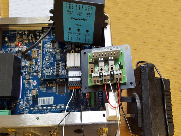
You will need to use an external DC power supply.
1.Connect the positive wire of the external power supply to PWC1 & loop to PWC2 & 3 if required on the RB3 relay module.
2.The GND wire of the external power supply will need to be connected to COM on the Baykon BX2X relay board.
3.For the fast feed connect a wire from output 2 to GND (PWC1) on the RB3 relay module.
4.For the slow feed connect a wire from output 3 to GND (PWC2) on the RB3 relay module.
And Finally...
We are planning our next Technical Scales Meeting to be held in May 2019 which will have focused working groups to get hands on with our products, look out for the email invitation and let us know if there is anything in our range you would like us to demo.
Thanks for reading the latest Tech Topics Blog post, as always you can
email me with any questions or call +44 (0)1284 701222.
Look out for the next blog post and let me know if there is anything you would like me to cover!